
When a Fast Stop Isn’t Fast: A Boston Minute on Bottlenecks
You pull into a busy lot on a cold evening by the harbor. The line looks short, so you think, “In and out.” The EV charger power module inside that cabinet thinks otherwise. The air is cold but the load is hot. Site data from mixed fleets shows that peak-hour sessions can slow by 15–25% when modules derate under stress. That is not your imagination. It is conversion physics, thermal limits, and grid noise teaming up on you—funny how that works, right? So ask yourself: is the charger slow, or is the way it moves power slow? We tend to point at the cable. The real friction lives upstream, in the power path and its controls. And it is fixable.
Here’s the question: what part of the module design actually moves the needle on real-world speed and stability? Let’s unpack the quiet culprits, then compare what the next generation is doing to make those winter nights less of a wait. Onward.
The Hidden Cost of Conversion: Where Traditional Modules Fall Short
What breaks first?
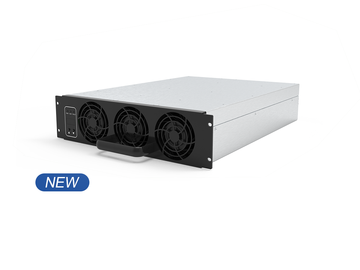
Direct answer first. Legacy topologies waste time and heat at the conversion stage. That’s where AC to DC power modules 30 enter the chat. They sit between the grid and your battery, bridging 3‑phase AC and a high-voltage DC bus. If the power factor correction (PFC) is sluggish, or the rectifier stage is hard-switched, you pay in heat and harmonics. Heat triggers thermal derating. Harmonics raise total harmonic distortion (THD). Both cut power right when you need it. Look, it’s simpler than you think: slow control loops and clunky switching mean longer dwell. Good hardware with weak firmware still stumbles. And poor EMI filter design can make the utility cranky and your uptime worse.
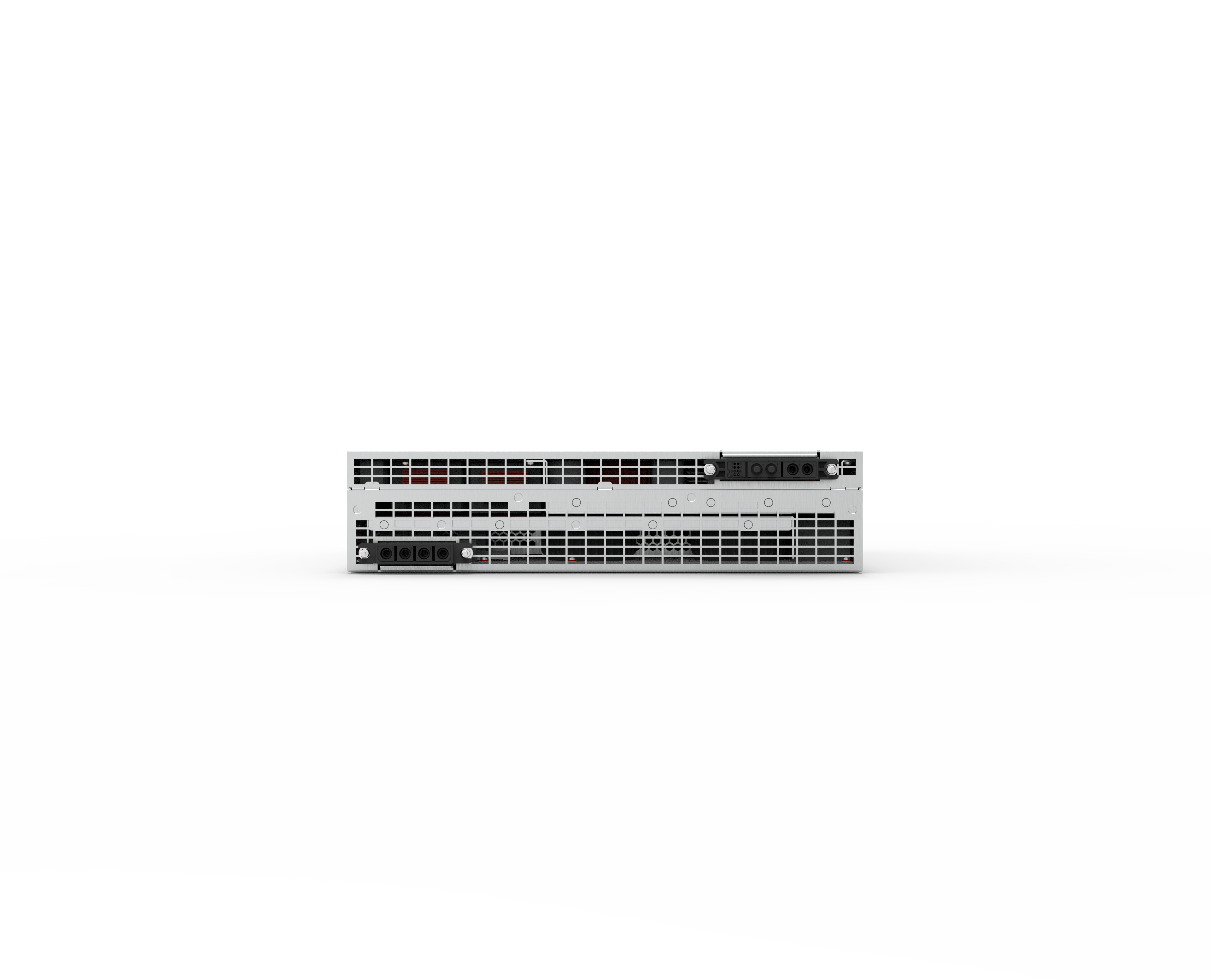
Now the sneaky bits. Many units share current across stacks without smart balancing. That leaves one module hot and another coasting. It hurts mean time between failures (MTBF) and makes service calls pop up in streaks. If the design lacks galvanic isolation margins or skips fast fault detection on the DC bus, a transient can ripple through to the pack. The result is nuisance trips and lost sessions. Add in narrow CAN bus bandwidth for telemetry, and you fly blind during faults. You’ll also see ripple current drive up I²R loss at the output stage. Old-school power converters can push a decent kW rating on paper, but under real load—cold-soak starts, voltage sag, long cables—they slip.
Looking Ahead: Smarter Power Paths and Why They Win
What’s Next
The better path uses new switching devices and control brains that think fast. Silicon carbide (SiC) MOSFETs with soft-switching, like an LLC resonant DC/DC stage, cut switching loss. Faster PFC controllers hold unity power factor even when the grid jitters. The control loops sample quick and act quicker. That keeps the DC bus steady and the cable cool. Add model-predictive control, and you spot spikes before they land. A high protective charging module also raises the floor for safety. Class B insulation, tight isolation clearance, and hardware interlocks stop faults at the module, not the charger cabinet. It’s containment with brains—and less downtime.
Thermal is the other half. Better modules spread heat with liquid plates, tuned airflow, and smart derating curves. Not just “drop to 70% and hope.” Instead, they coordinate across parallel stacks so no single unit cooks. Edge computing nodes at the site can arbitrate load sharing. They learn patterns, like lunch rush or game-day spikes. Firmware updates push improved transient response without new metal. And yes, that makes life kinder for cables and contactors. The net effect is repeatable charge time, even when the parking lot is slammed. More stability, less drama — and fewer apologies to the next driver in line.
How to Choose Without Regrets
Here’s the boil-down, without fluff. We saw that older designs lose time at conversion, stumble under heat, and hide faults until you feel the pain. Newer modules tighten control loops, cut loss with SiC, and isolate failures. They share load better and talk to the site in real time. So how do you pick the right box when spec sheets all look the same—funny how that happens?
Use three checks that are hard to fake. First, control speed: verify transient response from 10% to 90% load, plus recovery time under a 5% DC bus dip. Second, thermal honesty: ask for derating curves at ambient extremes, and confirm coolant flow assumptions match your cabinet. Third, noise and safety: demand THD at full tilt, conducted EMI plots with the actual filter, and proof of fault isolation time to shutdown. Bonus points for field logs that show uptime during peak hours. If a vendor hits those with room to spare, the rest falls into place. Keep it simple, keep it measurable, and you’ll keep your queue moving. For more context and options, see winline EV charger.